 [1]Here’s the latest chapter on our ratty, matte white 1954 Chevy – Project Sucker Punch [2]. Suspension components from the 1950s were very basic; they hadn’t gotten much better than the prior decades and we all know that these old Chevy’s ride on what is essentially horse and buggy technology. We decided to ditch the 60-year-old front and rear suspension and replace them with new components from Total Cost Involved Engineering [3] (TCI).
 [4]
[4]Our 1954 Chevy Bel Air showed up with a trunk full of goodies.
TCI Engineering has been around for forty years and are well known as the go to guys for bringing your rod into the twentieth century. We went with the 1949-1954 Chevy Street Rod front suspension kit [5] and the 1949-1954 Chevy Car rear parabolic leaf spring suspension kit [6].
These kits are very affordable, and aside from a bit of welding, the transformation is fairly straightforward and can be done with common hand tools in your garage. We handled the suspension upgrade in house, but if this type of work is over your head, the job can be performed by a local shop with suspension experience.
A little refresher course on our old Chevy project car is in order here to bring things up to date. Our 1954 Bel Air 4-door, aka Sucker Punch, is running a Blueprint Engines [7] 383ci short-block topped by an Edelbrock [8] DIY Performer RPM E-TEC 435 upgrade kit (JEGS part #350-45909 [9]). All of that power is backed up by a Hughes Performance [10] TH350 transmission (JEGS part#512-35-2 [11]).
With the addition of a complete TCI Engineering front and rear suspension, rack and pinion steering, front disc brakes, and a fresh Currie [12] rearend, Sucker punch will have safe, modern, up to date running gear to lay down all that power.
Checking Out The New Parts
Getting ready to upgrade the entire front suspension from the brakes to the rack and pinion steering, this will make Sucker Punch a little more fun to drive and less of a chore to maneuver.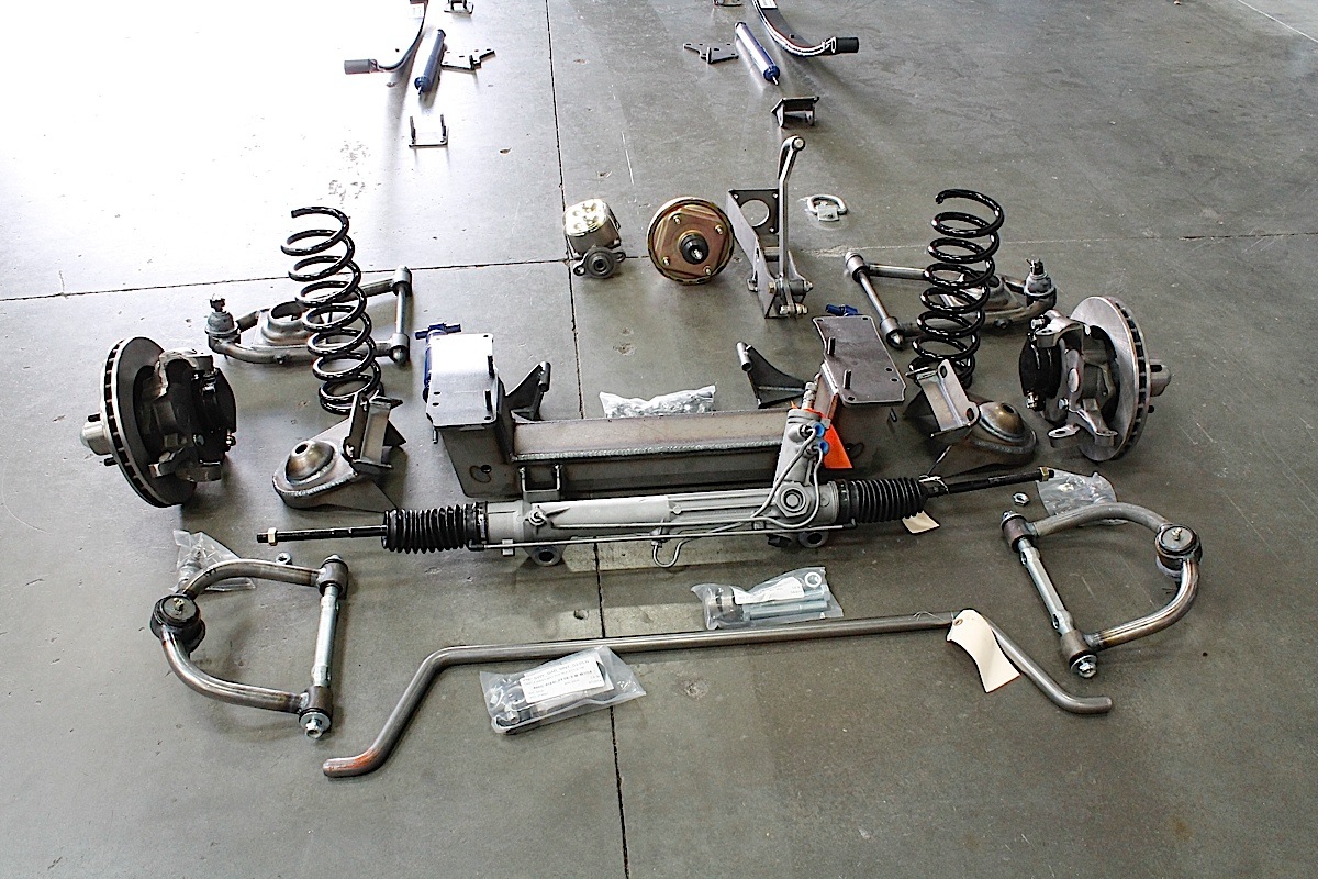 [13]
[13] [14]
[14]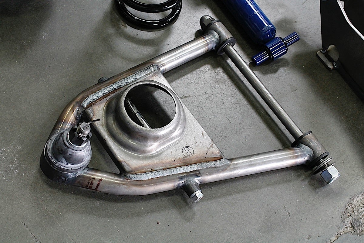 [15]
[15]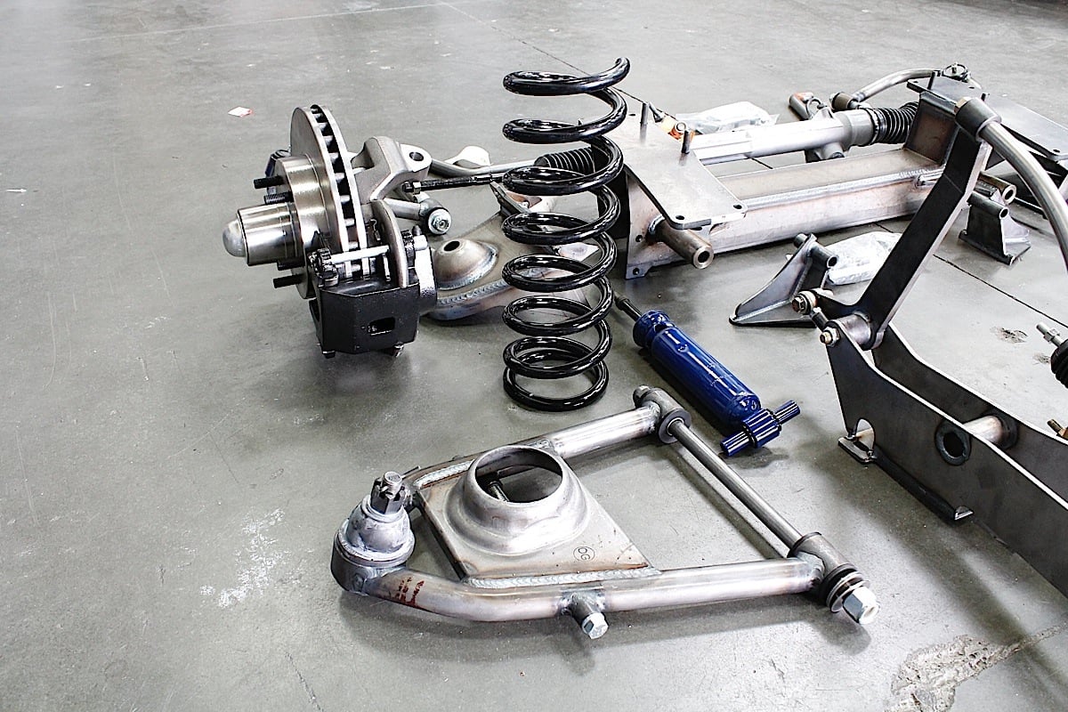 [16]
[16]
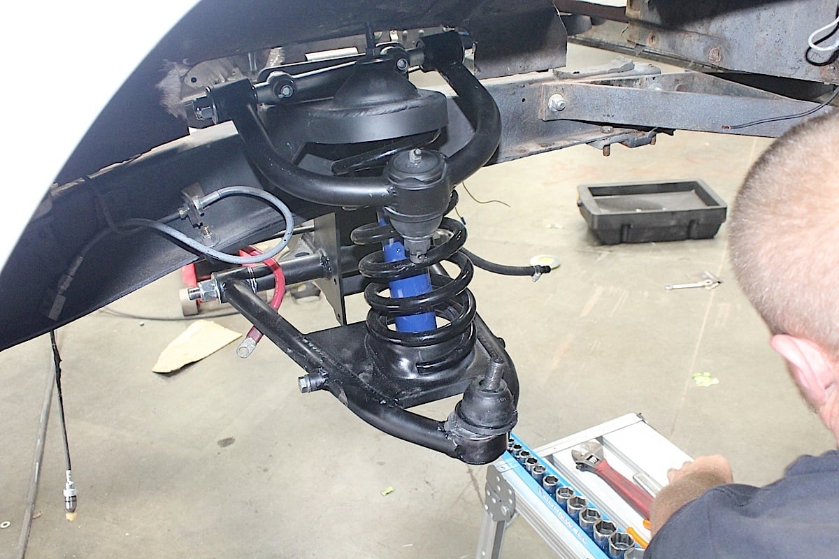
The front suspension kit [6] consists of a crossmember, upper and lower tubular control arms, rack and pinion steering, tie rod ends, spindles with 11-inch rotors, and a sway bar. The kit also comes with a new master cylinder set-up complementing the new front brakes. Going from four, outdated drums to a front disk/rear drum setup meant the upgraded master cylinder was a necessity.
Installation is fairly straightforward with easy to follow instructions. Most of the new components bolt into existing factory locations. There is some drilling required, but the ability to pick up most of the original cars mounting points really helps in locating parts correctly. As you might guess, this does require a bit of skill, even without the welding that needs to be done.
TCI recently re-engineered the upper coil-spring tower to accommodate a traditional shim style alignment adjustment instead of T-bolts. The new design now uses a vertical plate to mount the upper control arm. During this redesign we were also able to increase camber and reduce dive for better performance during cornering and stopping.
The main channel is made from 3/16-inch thick ASTM A-1011 steel plate and is completely welded in house for quality control. The new lower control arm mounting pin is a one piece design for added strength and durability without increasing weight. Heavy duty ball joints and control arms are employed for extra strength and reliability.
 [17]
[17]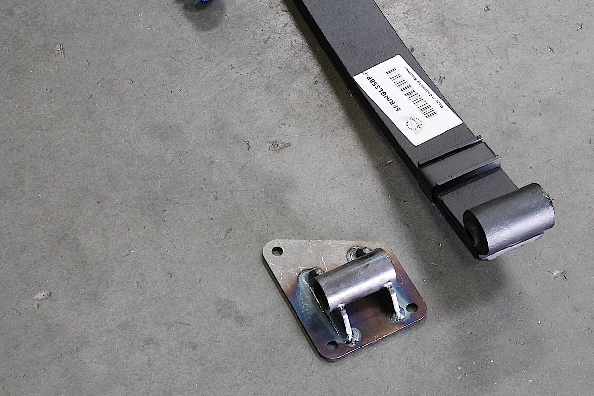 [18]
[18] [19]
[19]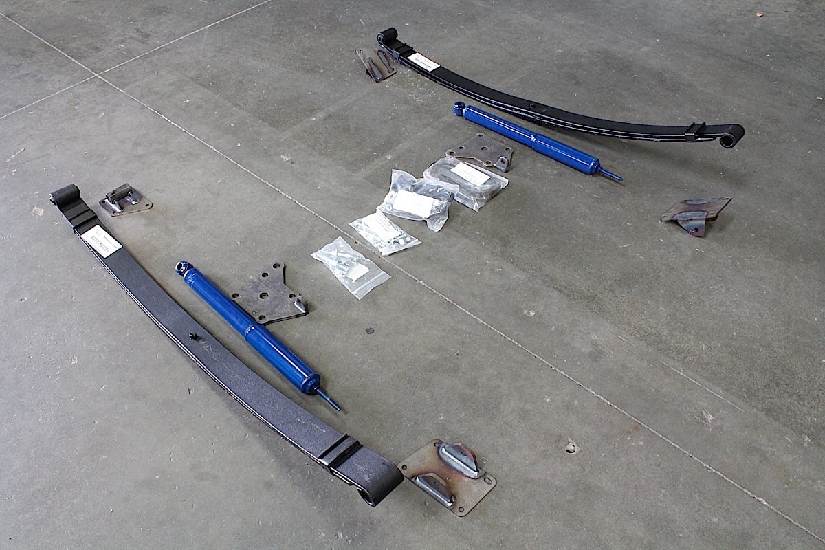 [20]
[20]
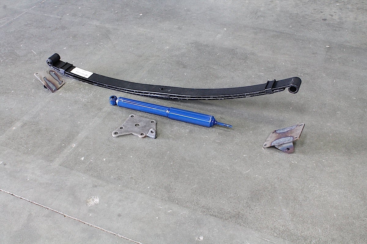
The TCI Rear Suspension Kit (# 424-4610-00) consists of parabolic leaf springs, shock absorbers, hangers, mounting shackles, U-bolts and hardware. While we had the car apart we decided to replace old rearend with a new Currie unit and upgraded drum brakes.
The rear suspension kit [6] provides the vehicle with strength, durability, proven quality, greater flexibility, 28% weight savings, and better fuel mileage with less vehicle weight. This leaf design is characterized by fewer leafs with thicknesses that vary from center to ends, following a parabolic curve.
The characteristic of parabolic springs is a better ride quality and not being as “stiff” as conventional multi-leaf springs. The end result is light, strong and simple, yet brings the ride and handling characteristics into the twenty-first century.
 [21]
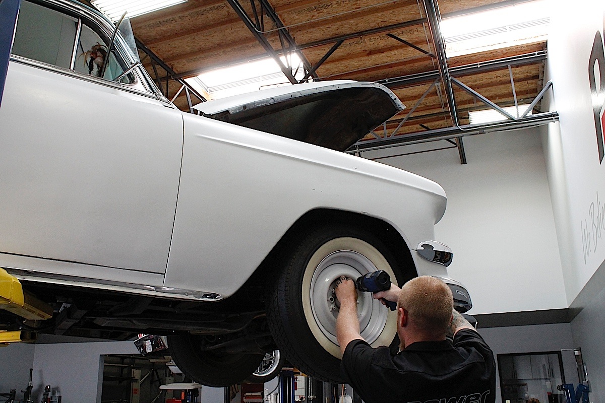
[21]With the ’54 Chevy up on our BendPak XP-10ACX lift [22], the tear-down process began in preparation for the TCI Engineering suspension swap.
Tearing It All Down
We used standard tools here including hammer, chisels, screwdrivers, grinders, wrenches, sockets, and ratchets and got down to work. We did some measurements before putting the car up on the rack and removing all four wheels. The original front suspension has seen some updates with new bushings and a disc brake conversion, but remained mostly stock. We started by removing brake lines, sway bar mounts, and the idler arm from steering linkage.
The old IFS has only four bolts per side holding it in place. After breaking the crusty old studs free, a jack is placed underneath the center of the old crossmember and the bolts are finally removed, using the jack to support the load. The entire crossmember assembly is lowered down and set aside.
60 years of crud and rust always slow things down. Make sure you have penetrating fluid and mallet handy. [23]
[23]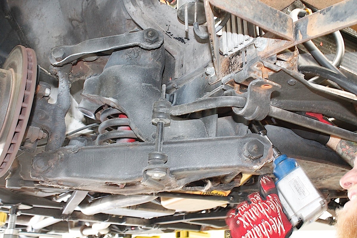 [24]
[24] [25]
[25] [26]
[26]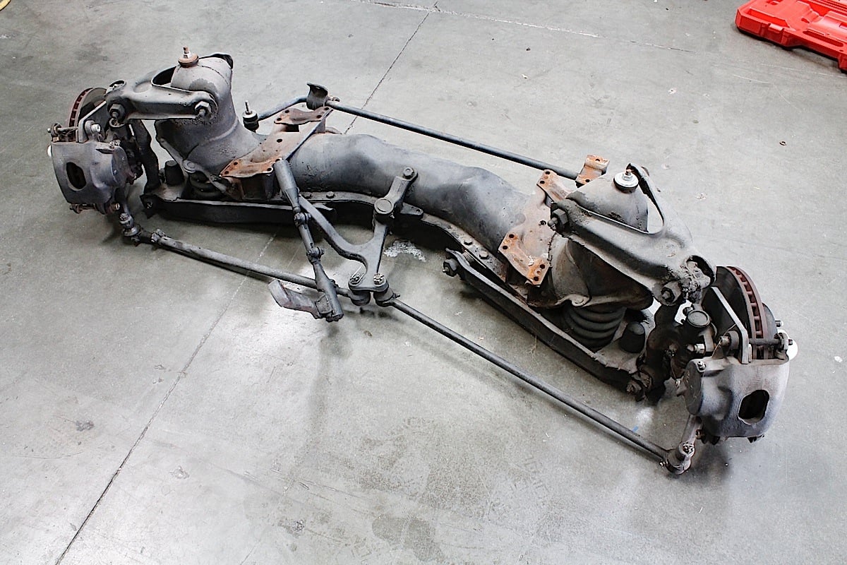 [27]
[27]
With the front removed, the old rear suspension followed. The original setup had lowering blocks and longer U-bolts holding the axle to the springs, but other than that it was fairly stock. We disconnected brake lines, unbolted spring hangers, and rear leaf springs, and attacked the shocks making sure to support the rear axle with a floor jack.
The driveshaft was unbolted from rear axle and removed as well. When removing the rivets from the front and rear leaf spring hanger brackets on the frame, we used a grinder to grind down the heads of the rivets, then used a hammer and chisel to tap them out.
The exhaust system was unbolted mid-chassis to help free up working space and create easy access for installing new components. Once the exhaust, rear axle assembly, and leaf springs were removed, both systems were lowered together killing two birds with one stone.
Tearing down is the easy part. Taking notes or pictures and following instructions goes a long way when beginning install .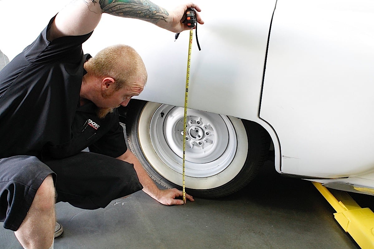 [28]
[28]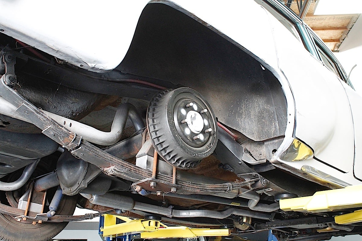 [29]
[29]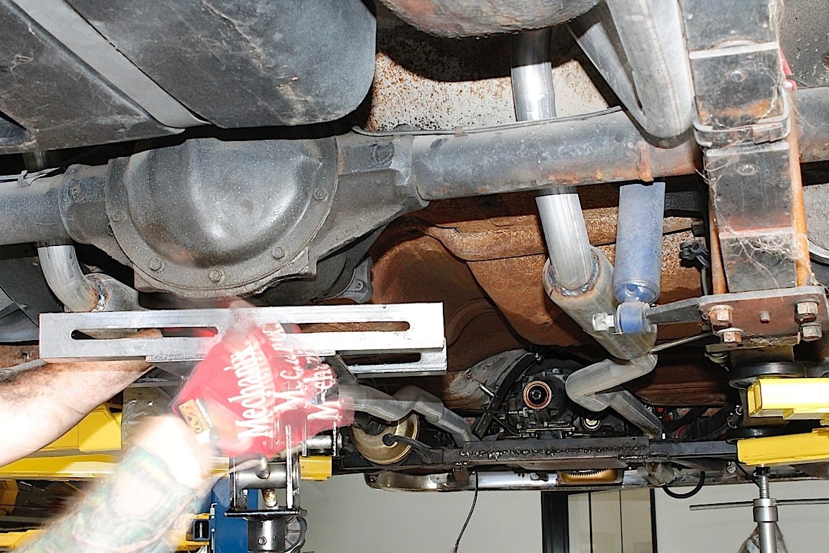 [30]
[30] [31]
[31]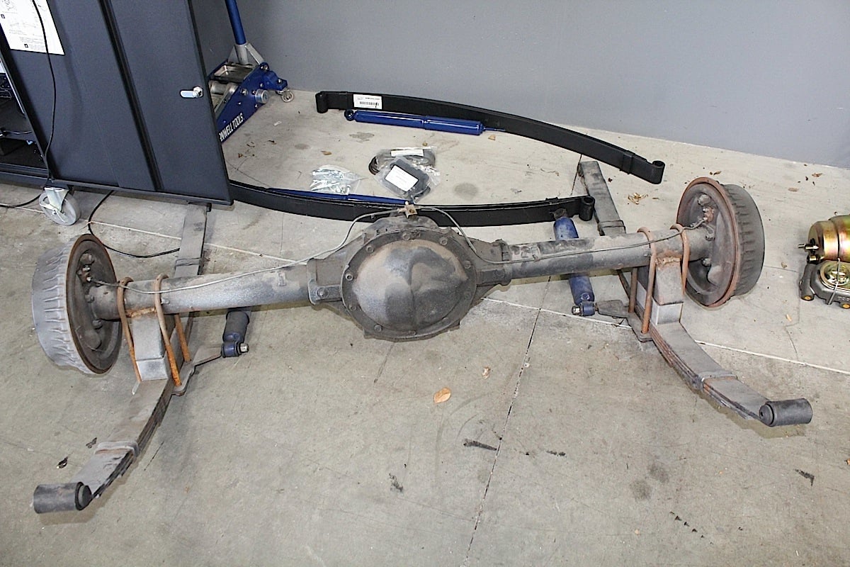 [32]
[32]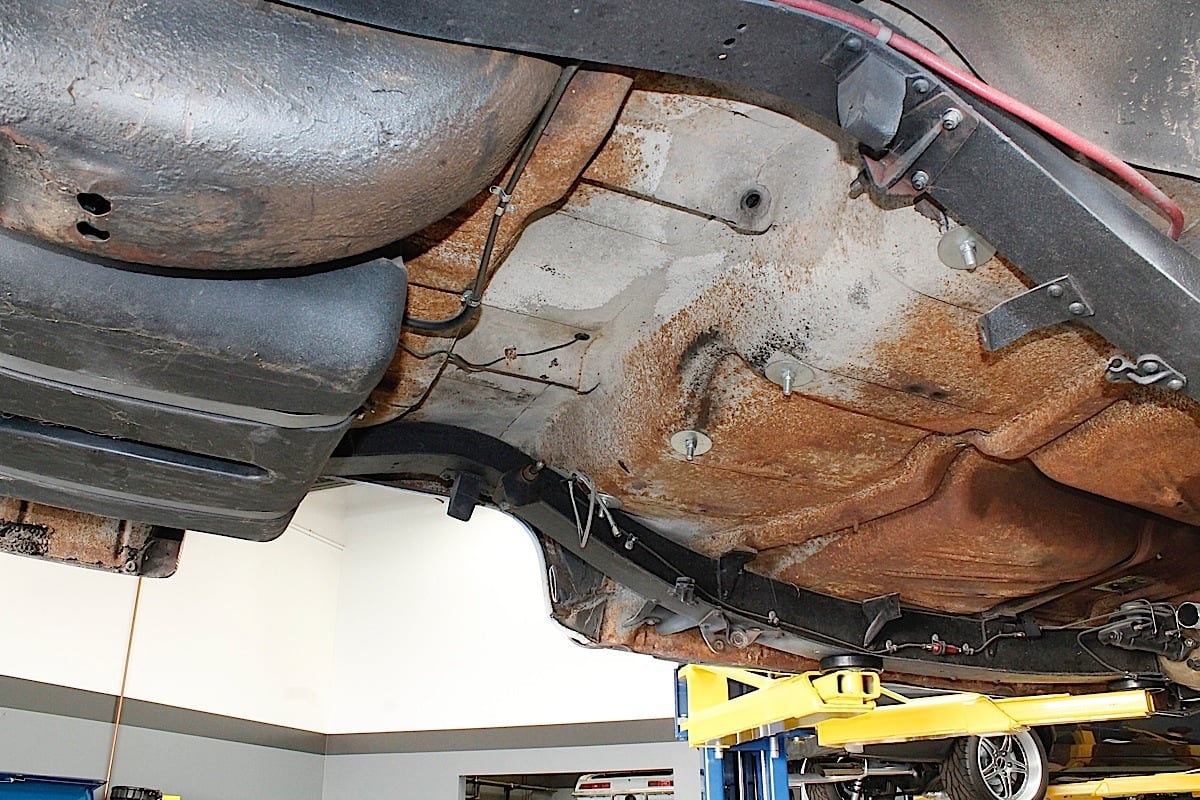 [33]
[33]
Replacing The Front Suspension
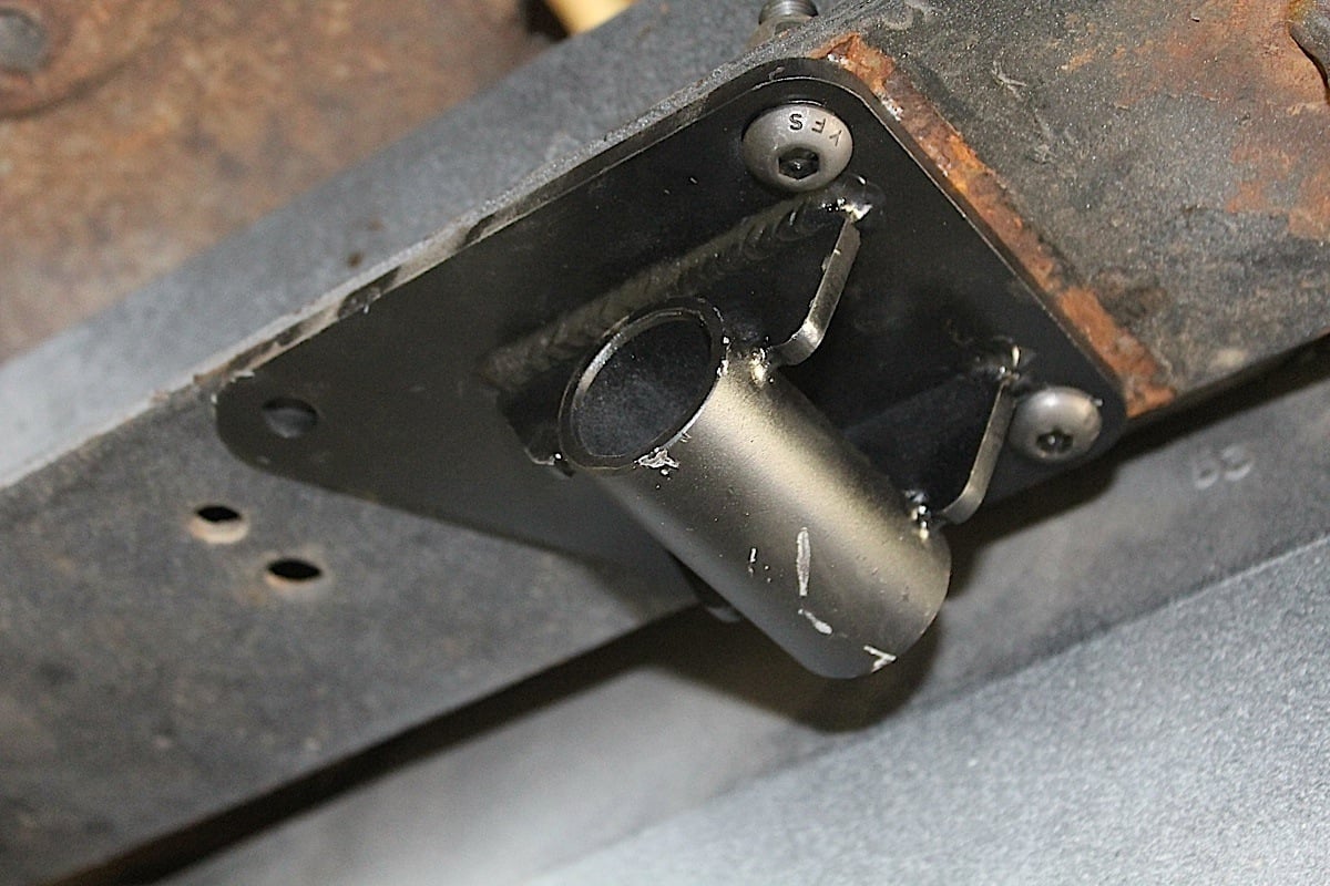
Taking your time and getting to know the mounting points on the front suspension kit will greatly ease installation. The crossmember is the foundation that all of the components are bolted to, so planning out the install is a good idea that saves time later. The crossmember has seven holes per side with five points matching up to existing factory holes. Only two holes per side needed drilling. The factory holes on the frame align the new piece exactly where it’s supposed to be, and that helps to line up the unit for the additional drilling.
 [34]
[34]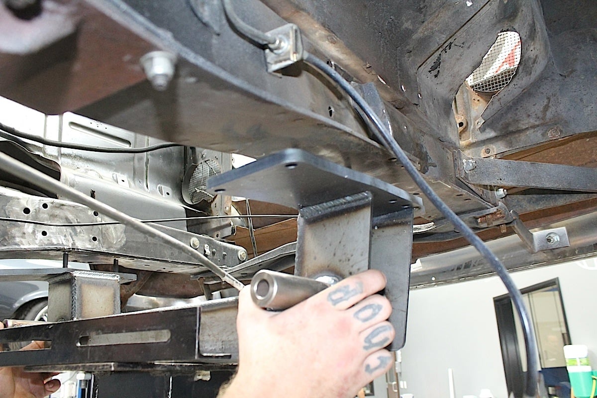 [35]
[35]
The front crossmember is a beefy unit that will bolt directly to the front rails, but also requires a bit of welding to secure it properly.
Because the bolts on the old crossmember faced towards pavement, removing them was easy. The new crossmember bolts in from above which conflicted with existing motor mounts. The engine and mounts were removed and the frame prepped by grinding smooth any welding marks left over from motor mounts.
The installation in the front is pretty straight forward with the included instructions. Setting the shocks may seem a little tricky for the first timer, however. We made sure that the shock can operate through the full length of travel with out binding. As with all of the new components, we made sure everything functioned properly after it was installed.
 [36]
[36] [37]
[37]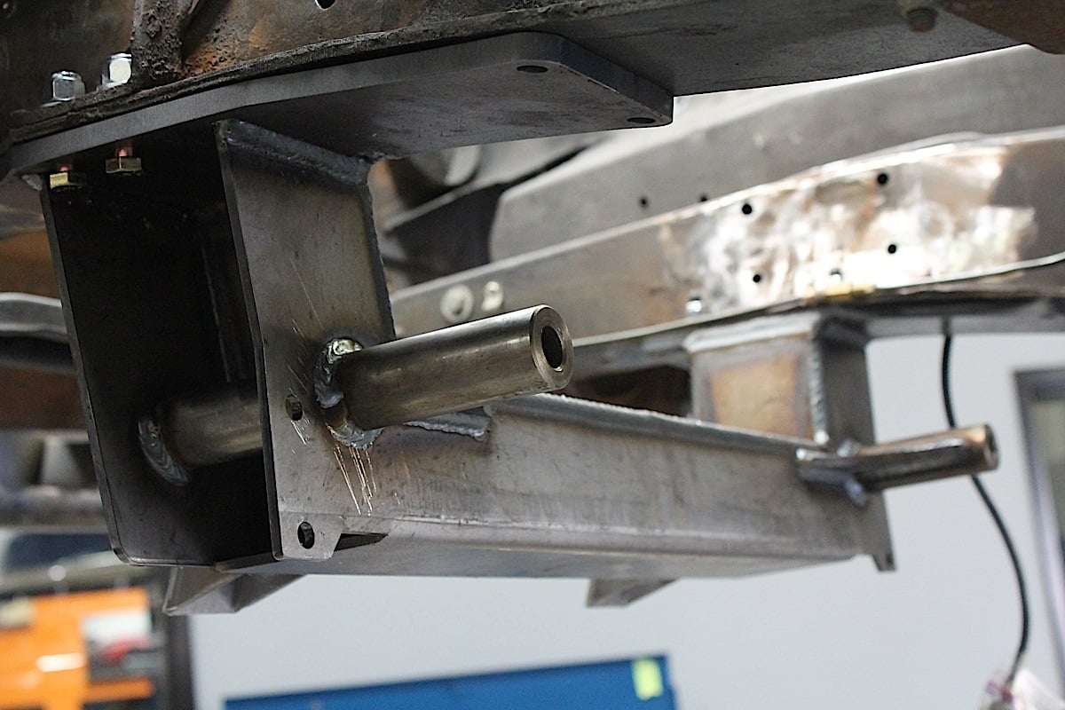 [38]
[38]
When working with a vehicle this old, keep in mind that not all chassis were identical from the factory, and over the years a car probably gets tweaked a little bit here and there. If a hole does not line up perfect, drilling it out a little bit can help, along with some measuring to ensure that everything is square.
After the crossmember was bolted in place, we had some welding to do. This part required a bit of experience and welding ability; it’s not for those who are just learning to weld. We reviewed the instructions once more to make sure we were familiar with the details of welding the two “spring hats” onto the frame. As the old saying goes, it’s crucial that you “measure twice and cut once” as these parts not only anchor the top of the shocks and springs, but the upper control arms as well.
The tall part of the control arm mount goes towards the front of the car. This is the built-in anti-dive. Follow the measurements in the illustration above for exact placement of the towers side to side & front to back. It will be critical that the towers are installed square and parallel to each other at 27-3/8 inches +/- 1/16 inches apart outside to outside of arm mount faces. Also, the arm mount face must be vertical +/- .5 degrees. This will insure proper alignment.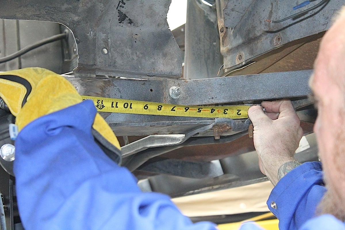 [39]
[39]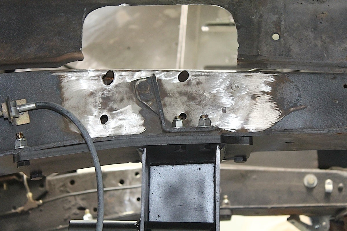 [40]
[40] [41]
[41]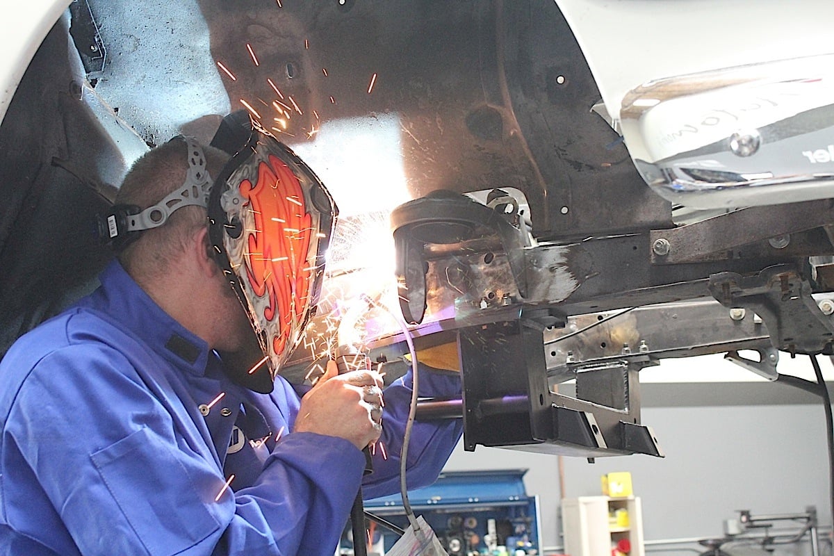 [42]
[42]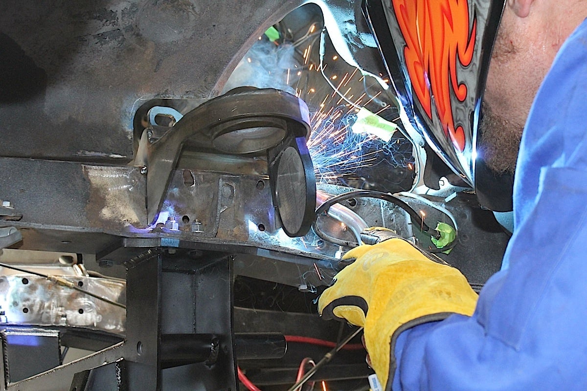 [43]
[43]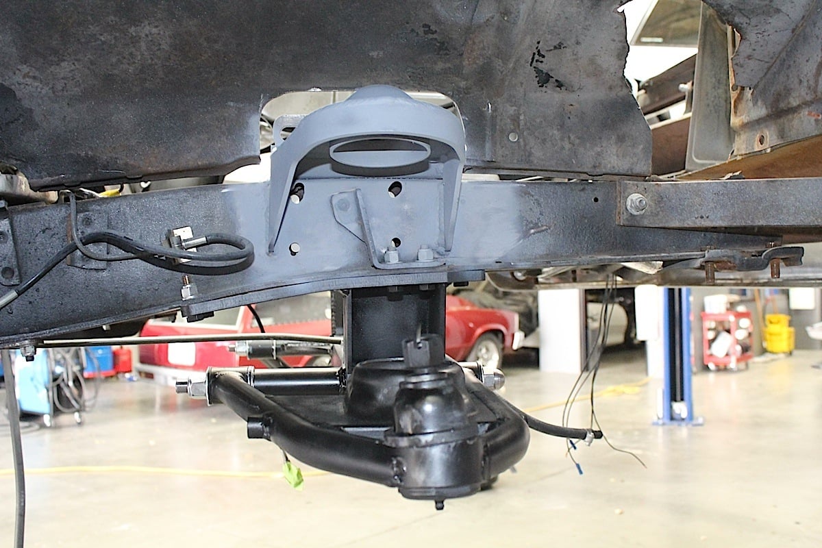 [44]
[44]
It may be necessary to grind some material off the towers where they come up against the side of the frame to achieve the proper measurement. As a reference, we installed the shock onto the lower control arm and pulled the shock shaft through the upper spring tower hole.
The shock shaft should line up directly with the hole in the upper hat when everything is correct. With the shocks mounted in the upper hat, we installed the lower control arms. The front suspension utilizes a coil spring that mounts over the shock absorber, and is held in place by the upper hat and lower control arm.
When installing the front suspension components, it's best to leave parts a little bit loose until everything can be lined up with slight adjustments being made.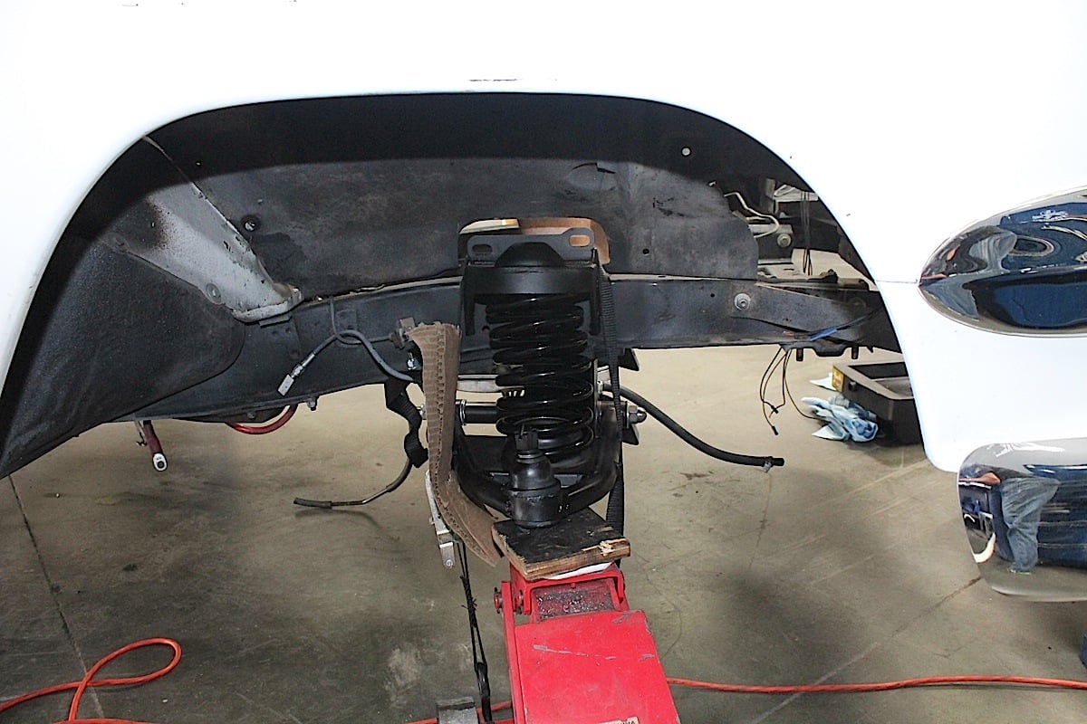 [45]
[45]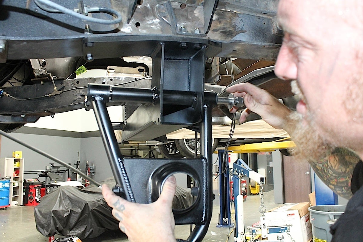 [46]
[46] [47]
[47] [48]
[48]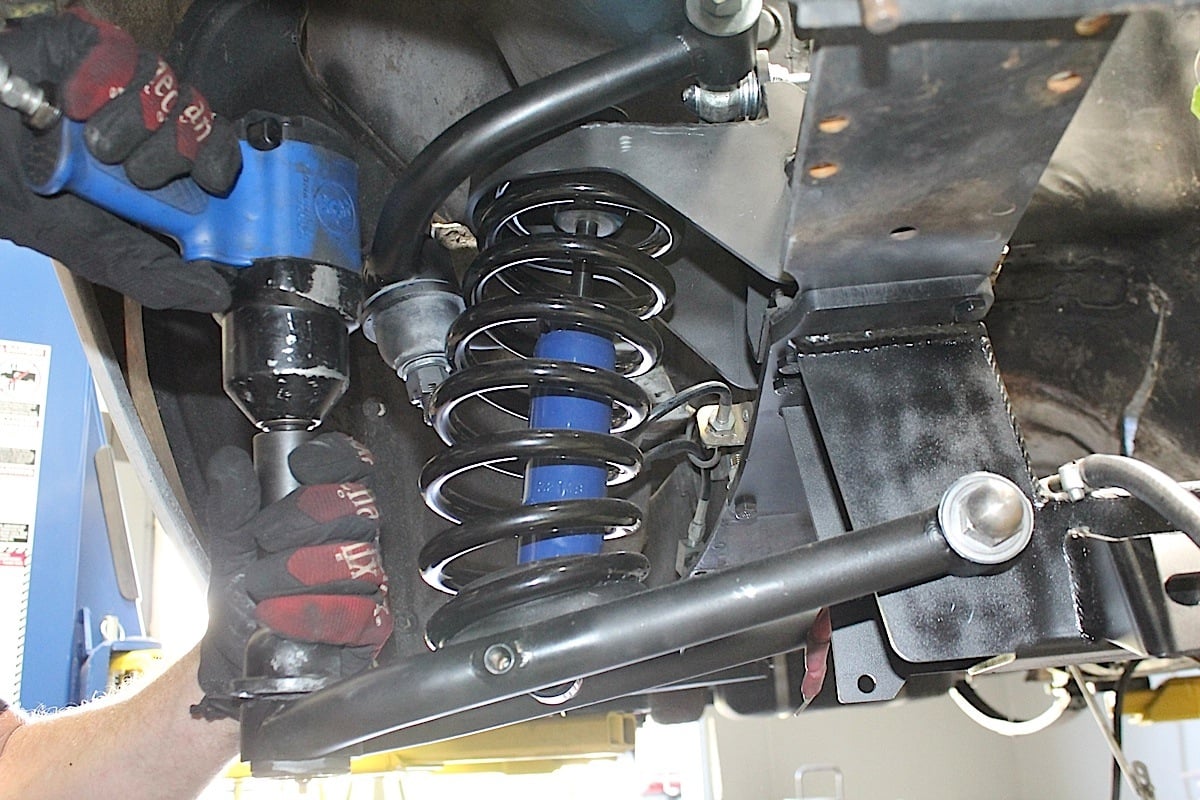 [49]
[49]
 [50]
[50]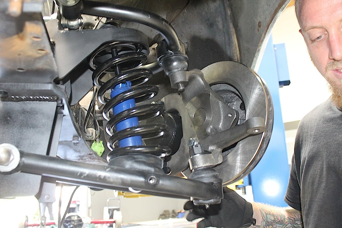 [51]
[51]
Place the spindle onto the lower ball joint with the steering arm facing forward with the large I/D tie rod end taper facing down; the tie rod end goes up into the spindle.
The tricky part was compressing the coil springs. Without a coil spring compressor, another method is to use a floor jack, as illustrated by our technicians. Note that safety straps were used as a precaution with this method. We can’t stress enough how critical it is to use caution here. For a novice, it’s probably safer to use a spring compressor.
 [52]
[52]It’s always recommended to use a spring compressor when installing coil springs, it makes the job much safer.
To compress the spring, it was positioned into the top end of the shock tower and we raised the lower arm and seated it to the bottom of spring. We compressed the spring and slipped the shock into the coil spring, and bolted it in at the lower control arm. We continued compressing the spring until the top of the shock could be bolted to the upper shock tower. After making sure the shock was bolted firmly in place, we removed our makeshift spring compressor/floor jack. With the arms in place, the next step was to bolt in the spindle to the upper and lower ball joints.
Place the ball joint washer first and then the castle nut. Torque the lower ball joint to 90 ft-lbs and install the cotter pin. The lower ball joint is a MOOG K719 (JEGS part #719-K719 [53]). Pull the upper control arm down onto the spindle. Place the ball joint washer first and then the castle nut. Torque the upper ball joint to 70 ft-lbs and install the cotter pin. The upper ball joint is a MOOG K772 (JEGS part #719-K772 [54]).
Installing The Rear Suspension
The rear suspension wasn’t as technical as the front suspension, but we still had some work cut out for us. The new brackets required a clean, smooth surface so we used a grinder to remove any left over material on the frame rails. The new mounting hardware was installed on the chassis using the supplied bolts.
 [55]
[55]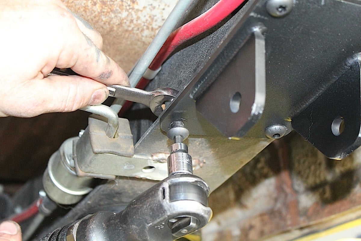 [56]
[56]
The spring hangers were bolted into place first, making sure that they could be mounted flush to the frame rails.
The new mounting plates were designed to be bolted into old OEM holes in the frame. We attached the leaf springs ahead of rear axle and left the hardware hand tight. With the proper support in place, we lifted the Currie 9-inch rearend and the leaf springs into position and installed the U-bolts (two per side) to the included spring plates.
The passenger side rear leaf spring bracket has tight access due to the spare tire well in the trunk. Patience and a crows foot attachment are a huge help here when installing the new brackets. Also make sure the new shackle bolts do not interfere with the spare tire well. 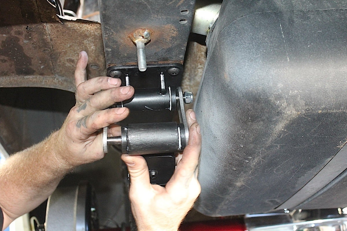 [57]
[57]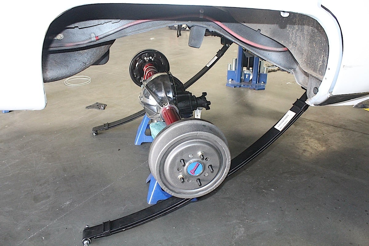 [58]
[58] [59]
[59]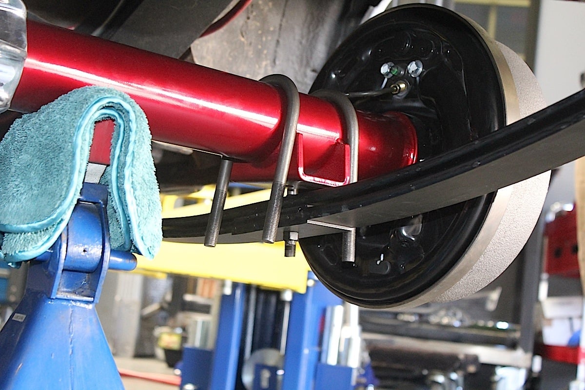 [60]
[60] [61]
[61]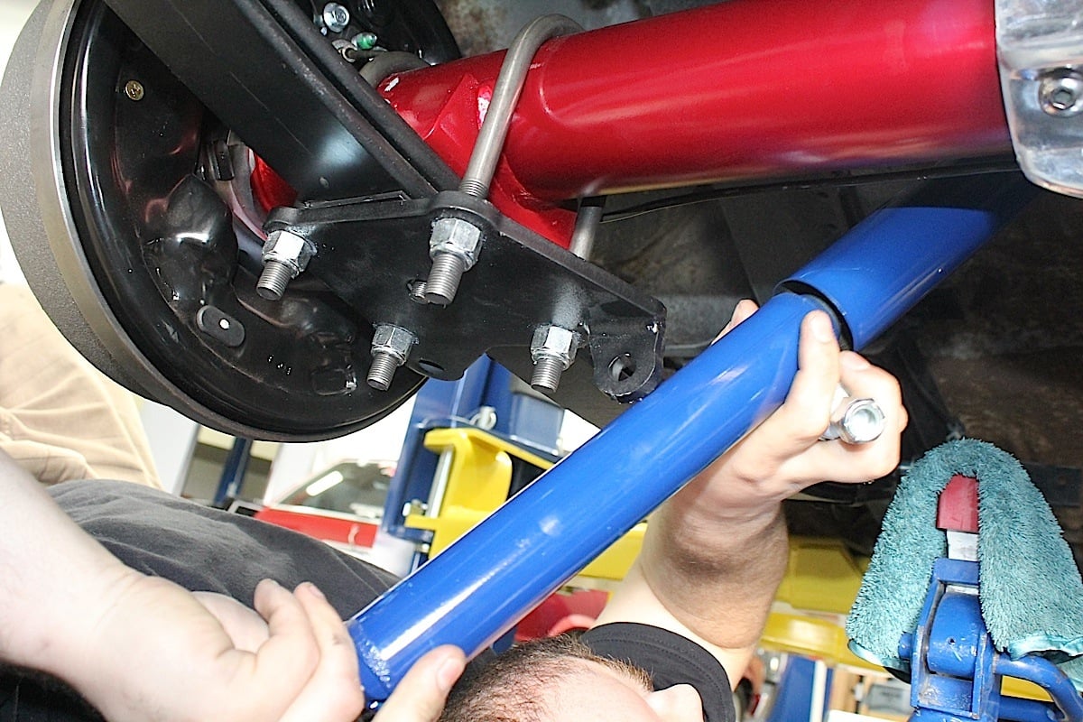 [62]
[62]
Finishing Up The Installation – Braking And Steering
The IFS kit also includes a new master cylinder kit which is mounted under the driver seat. Holes had to be drilled into the frame for a mounting plate before we could mount the master cylinder and plumb the brake lines. With the master cylinder low on the chassis like this, we needed to make sure to add residual valves in the brake lines to maintain pressure.
Because of its placement underneath the driver seat, an access panel must be added to the floor to make filling the master cylinder with brake fluid easier. If you are making your own, mark the cut-out that you will be using on the underside of the floor above the master cylinder. Once marked, remove the master cylinder and booster to allow more room for cutting and working on the floor. Make sure you use a cover for the hole and that it is secured in place before covering it with your carpet.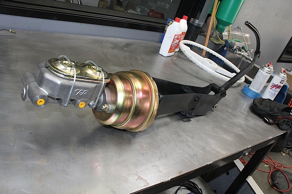 [63]
[63]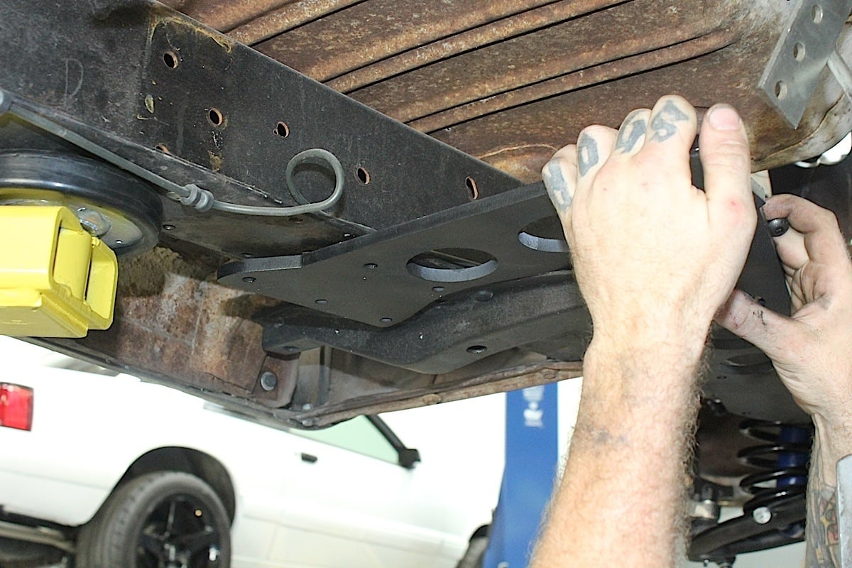 [64]
[64]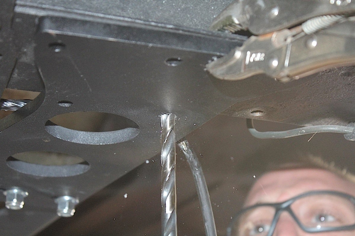 [65]
[65]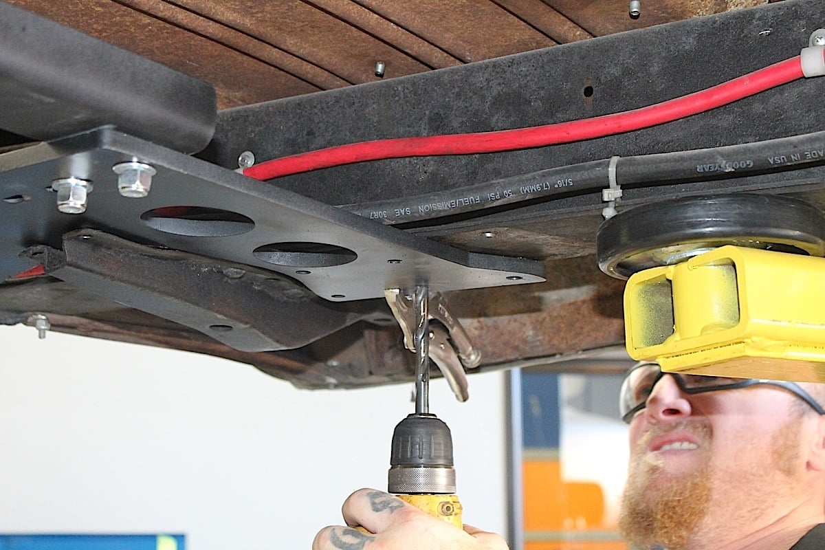 [66]
[66] [67]
[67] [68]
[68]
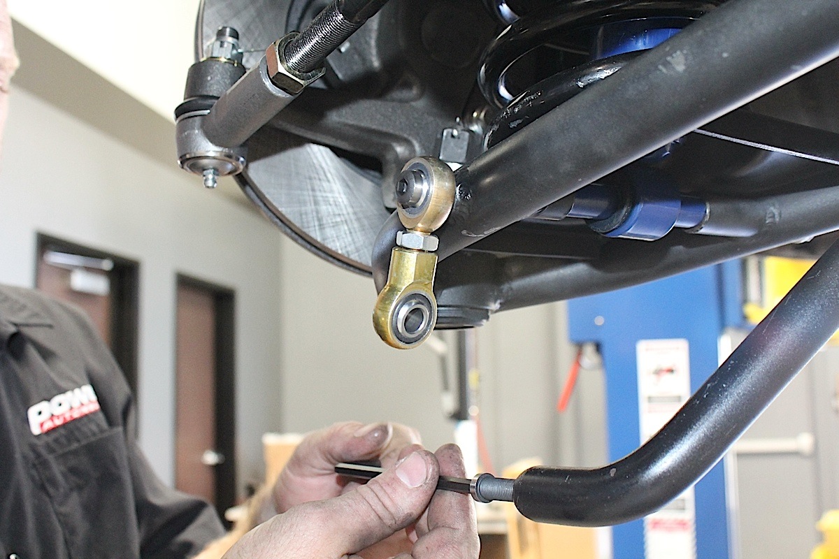
We installed the rack and pinion steering gear by centering up the rack and bolting it to pre-drilled holes in the crossmember using the included hardware. The sway bar mounted using the included hardware and we attached a slide-lock ring collar over each end and bolted it to the crossmember. The sway bar links are Heim joints attached to the control arms.
We placed the rack on the crossmember brackets as shown and used the supplied hardware to fasten it into place. The power rack shown requires a 5/8-inch spacer between the rack and the mounting brackets, however, a manual rack bolts directly to the mounting brackets. [69]
[69]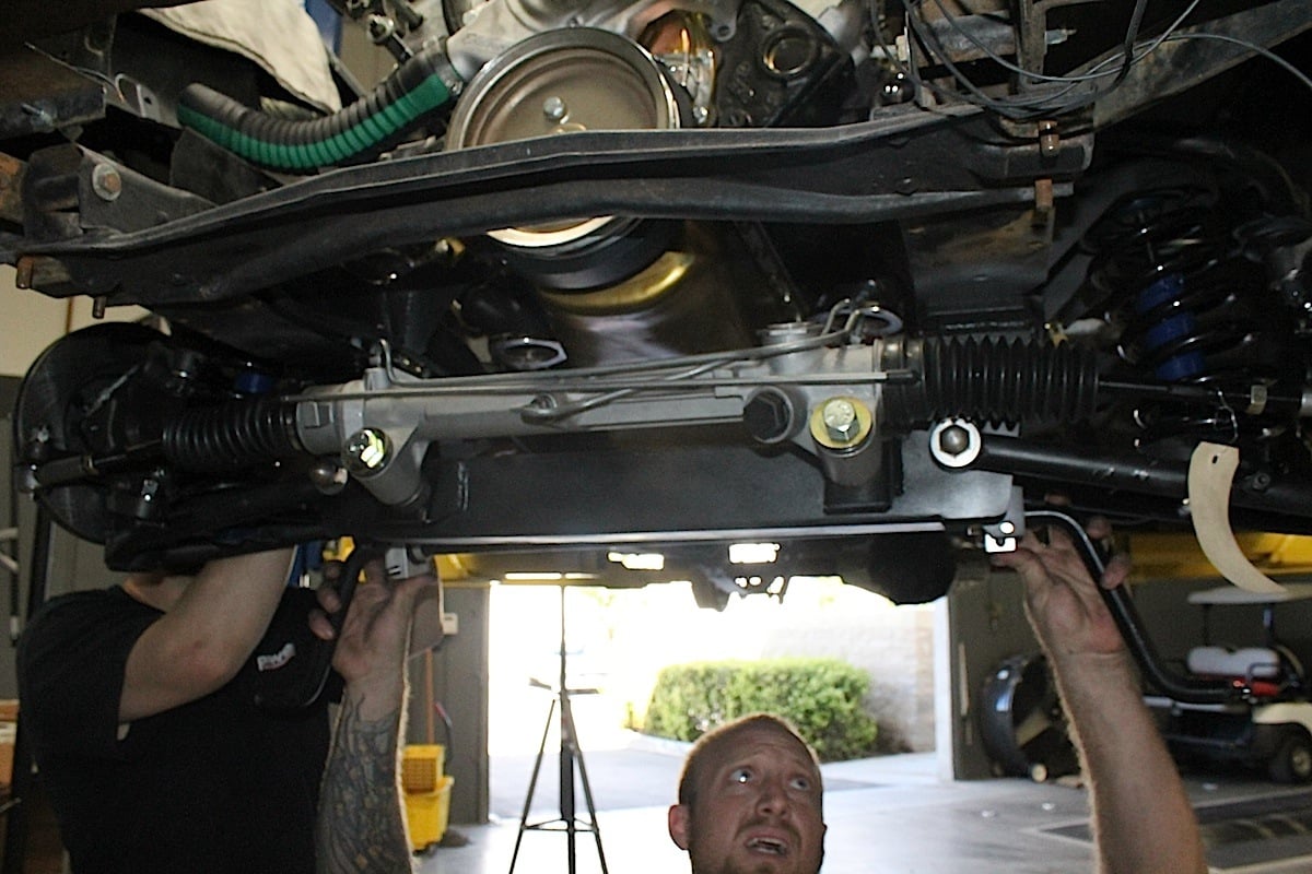 [70]
[70] [71]
[71]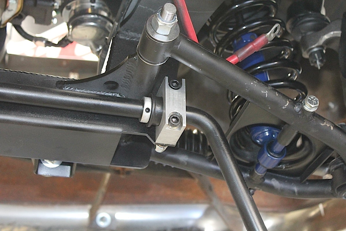 [72]
[72]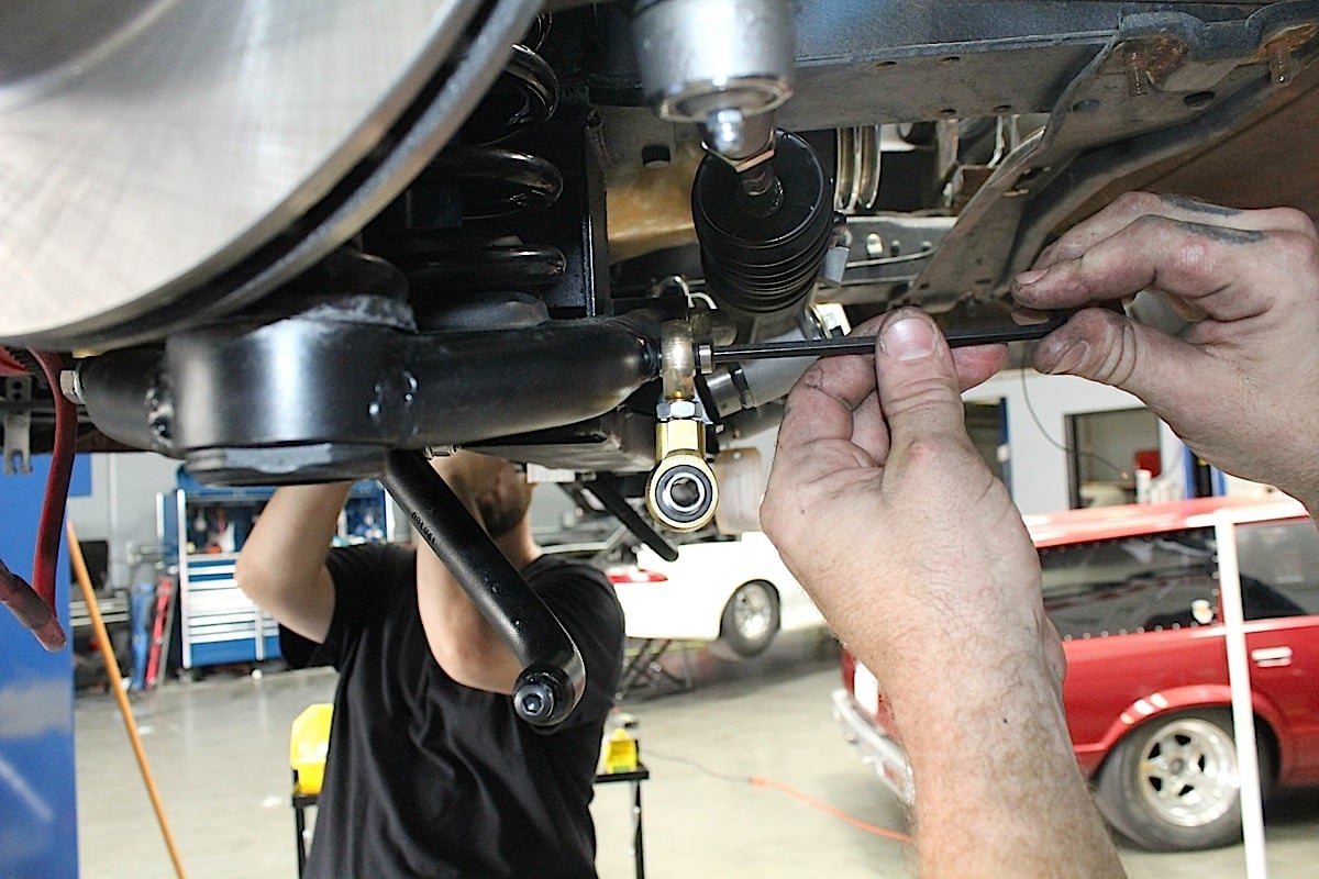 [73]
[73]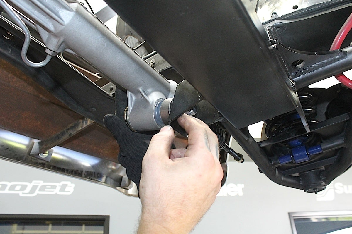 [74]
[74]
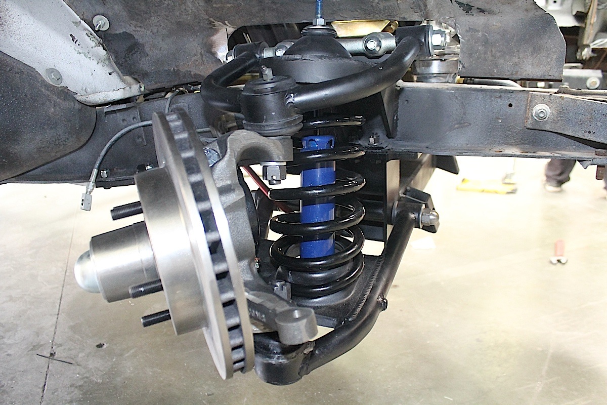
The end result is new lease on life for our old ’54 Bel Air. The project took a few days to complete, with the front suspension obviously taking more time. Sucker Punch was essentially running a suspension system too archaic for the upgraded powerplant. Now, it runs on a modern IFS with tubular A-arms, front disc brakes, and rack and pinion steering, while the rear has a strong, beefed up Currie solid axle rearend and all new leaf spring suspension.
 [75]
[75]Heim joints provide a solid mount for the sway bar and help to keep the handling firm.
The installation was fairly painless, and once installed and tweaked will provide years of safe, high performance driving. Remember that any time the front suspension is replaced, an alignment will be needed. It’s recommended to set it as close as possible at the shop, then immediately taken to an alignment shop, trailering the car if at all possible.
As an added bonus, Total Cost Involved Engineering provides another level of customer confidence with a new warranty program. TCI Engineering uses some of the best materials and workmanship in the industry and stands behind these parts for six years or 60,000 miles (whichever comes first).
Whether you spend $600 on a leaf spring kit, $10,000+ on a complete rolling chassis, or anything in between, they offer one of the best warranties in the hot rod and classic car business. The new warranty is in addition to the existing Lifetime Warranty on items Total Cost Involved Engineering manufactures in-house, with details on the TCI website [3].